
About Automotive Relay Wiring Harness, A huge energy spike can damage the electronics attached to it whenever you remove the electric connection from the relay’s electromagnet.
The problem usually solves by using replays with shorting diodes that can divert the energy back to the source while dissipating it in the form of heat.
Overall, relays can boost the performance of the electric system three to four times more than usual, making it reliable.
That’s the reason why experts choose them in automotive applications as well. Let’s see how it is useful in the automation industry.
What is an Automotive Relay?
Relays are a kind of switch that operates electrically, hence also called an electro-mechanical switch.
You can find them in almost all vehicles, including trucks, vans, trailers, cars, and boars.
To name a few places, you can find the relays in these systems.
- Headlights
- Gas Valves
- Interior lights
- Alarm Systems
- Windshield Wipers
- Warning systems, including hazard sense, seat belt fastening, and weight limits
The relay uses an electromagnet device to operate the switch mechanically and moves it to make or break a circuit.
Moreover, you can usually find the standard or a mini relay which are small cube-shaped devices in the automotive industry.
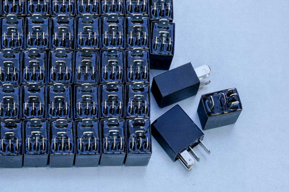
Caption: Relays with 5 terminals
Advantages of Using Automotive Relays
Automotive engineers incorporate relays in their vehicle systems for the following advantages.
Switch High Current Circuits
The relays can power a high-current circuit using a low-current system, which is handy when an in-line circuit switch cannot handle the higher circuit.
For instance, you want high-power work lamps in your existing headlight circuit.
Now the current circuit cannot fulfill the power need of the added object and exceed the capacity. Using relays in the scenario will solve the issue.
Execute Logical Functions
Car relays perform simple and complex logical operations like time-controlled and momentary functions.
For example, windshield wiper blades require such signals to initiate the work, so the interior light timing is delayed.
Recently the manufacturers have switched towards OEM rather than using the relays.
Still, relays offer cheaper alternatives than the former. Hence, most car enthusiasts choose relays to incorporate them into time-delayed functions.
Activate Multiple Signals through a Single Switch
Relays allow the activation of multiple circuits using a single switch. Hence, you can input the signal once, triggering many relays in the circuit.
These relays can further make or break the multiple circuits; hence, a whole series of operations occurs using a single input.
A common example of this scenario is the locking system of cars.
When you press the lock or unlock button on your car’s key, it applies the operation on all the doors rather than only one, making the work simple, effective, and time-saving.
Save Money
Not only are the relays time-saving, but they also save you a lot of money.
As you know, the relays can aid the low-current components to boost the signals for supporting high-voltage components.
Now, these low-current components are cheap compared to the high ones.
Hence, using relays means lowering the use of high voltage in the circuitry while saving you a lot of money.
Also, it can prove that you can build a quality circuit using inexpensive components.
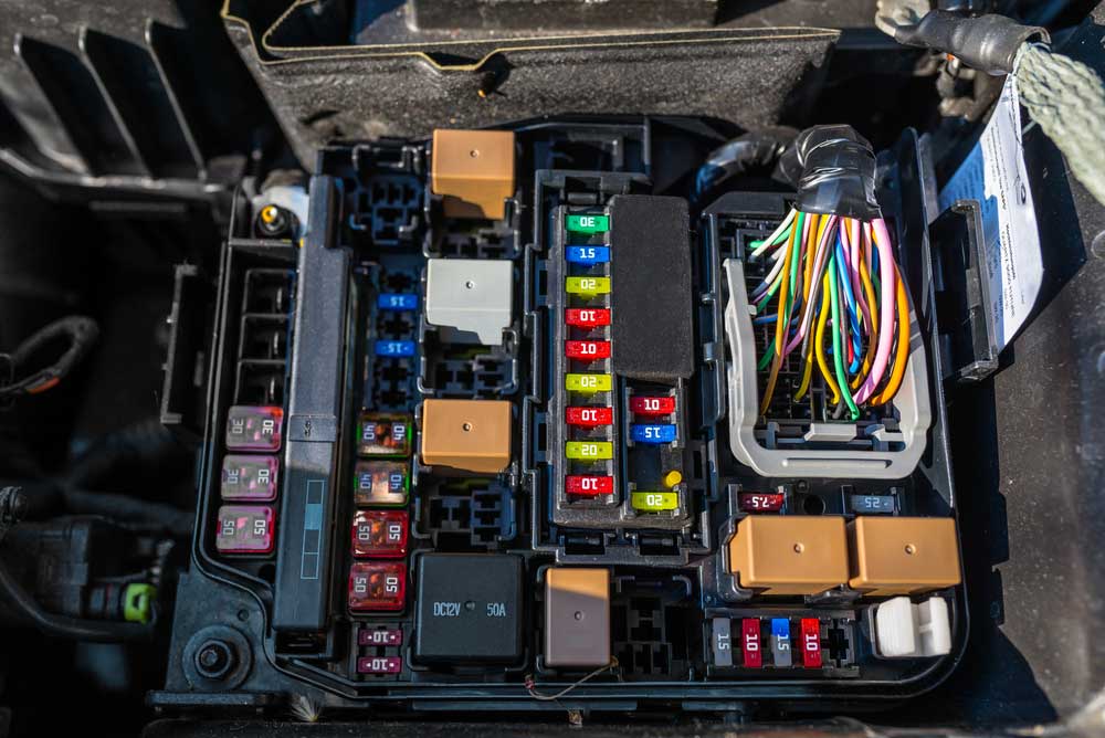
Caption: Relays in Fuse box engine compartment
How Does the Automotive Relay Work?
The Operation of the Relay Switch Mechanism is not as simple as it seems.
The electromagnetic relay consists of a wire coil that wraps around a solenoid, a soft iron core.
Also, it has a moveable iron armature, along with different contacts and reluctant iron yolk.
The number of contacts differs as the design and functionality of the relay change.
As far as the yolk is concerned, it has a hinged armature that connects to the moveable contacts.
A single spring sets the armature in its initial position.
When no power supply is attached to the relay, it de-energizes, causing an air gap in the magnetic circuit, thus opening it.
That’s how the circuit opens and closes all over the journey.
Some automotive relays have two contacts since different applications require different relays.
In such a case, when one is open, the other is closed. Furthermore, as the current reaches the solenoid, it generates a magnetic field which also triggers the armature for making or breaking the circuit.
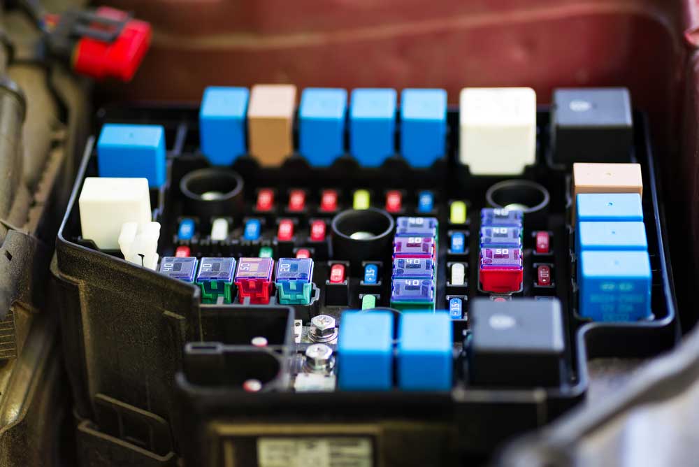
Caption: Relay application Close-up
Types of Automotive Relays
While there are different relays, the automotive industry uses two types in manufacturing, mini and micro relays.
Standard / Mini Relays
Standard relays can be divided into Make and Break and Changeover relays.
Make and Break Relays
A make-and-break relay has a high-current circuit with 4-pin terminals. Here, the contact is either Normally Open (NO) or Closed (NC).
The position changes when the circuit is on and off. Also, you can manually close or open the circuit using a toggle or a push button.
Change Over Relays
Changeover relays use two switches and five termination pins. Rather than operating one circuit, it uses alternative circuits while opening one and closing the other.
You can find its example in headlights, where you can alternate between high and dipped beams using such relays.
SPST vs. SPDT
Make and break relays also work as SPST (Single Pole Single Throw) relays, while the Changeover relays are referred to as SPDT (Single Pole Double Throw) relays.
| SPST | SPDT | |
| Relay Coil and contact terminology: Relays get their names under the DIN 72552 identification system, which defines the pins and terminals of a system clearly. Some of these codes are | 85 Relay Coil -ive86 Relay Coil +ive87 Common contacts30 Feed/Line in Positive | 85 Relay Coil -ive86 Relay Coil +ive87 Common contacts87a Normal Closed Contacts (NC)30 Feed/Line in Positive |
| Terminal Layout: As for the terminal layouts, the relays have two kinds, Type A and Type B. In both types, the position of terminals 86 and 30 swaps with each other. | 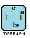 |  |
| Wiring Schematics: Type B is easier to connect as the terminals are in-line, making the connections easy to understand. | 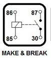 |  |
Note: Terminal widths also change as the type of relays varies.
For instance, most 4 and 5-pin switches use a 6.3mm width of terminal, while the other might use 2.8mm, 4.8mm, and 9.5mm.
As the terminal gets wider, it supports high-current circuits better.
Thus you will see the 9.5mm ones on the starter motor solenoids and the smaller ones on low-current signaling systems.
Either way, you should consider the switch and its terminations so that you replace it with the appropriate one.
Micro Relays
Micro relays are smaller than mini relays and are best when you have compact spaces for installation.
These relays are smaller than the regular cubed shape mini relays and have different ID systems to recognize who is who.
Here is a list of some common micro relays that you can find.
| Micro relays | |
| Relay Coil and contact terminology: | 1-4.8mm Coil2-4.8mm Coil4-4.8mm Normally Closed (NC)3-6.3mm Common Connection to Terminal5-6.3mm Normally Open (NO) |
| Terminal Layout: |  |
How to Wire a Relay Harness
Here we are taking a micro relay, for example.
- Remove the battery to disconnect any electrical supply.
- Fix the relay on an access point. If the area is prone to moisture, it is best to use waterproof jackets.
- Place a ring connector over a 12-14 AWG (red) wire. With its help, connect the positive terminal of the 12V battery.
- Attach a spade connector on the other end of the wire and insert it on terminal 3 of the relay. Also, add one spade connector on the “power” wire of the accessory you will connect.
- Take a 16 to 24 AWG black wire and crimp a spade connector on its one end. Insert this end to the relay terminal 2. Fix a ring connector on the other end and connect it to the nearest ground.
- Take one more wire with a spade connector attached and insert it into relay terminal 1. The other end of this wire will go to the power source. You can add a switch if needed in this wire.
- As you have wired every terminal of the relay, it’s time to reconnect the battery. After that, start the ignition and check terminal 5 (which has no wire connection) with a multimeter. The voltage rating should be 12V or near that.
- Connect the accessory’s black wire to the closest ground and finalize all the other connections.
And that’s how you will fix a relay properly. Remember that you will hear a clicking sound when the relay turns on. So there is nothing to worry about in it.
Conclusion
Relays have their significance when it comes to automotive wiring.
While there are different relay types, the harness method will also differ on the type.
Getting custom cables made at discount prices is now easier with Cloom Tech in the field.
Cloom offers the best wiring products under expert supervision to enhance the quality of your system. For further details, contact us now.